Led matrix hack story
At Le Loop hackerspace, we often get broken, old or unwanted weird devices. Then recently we were given two Led Matrix displays with a technology from the 80s.
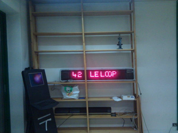
First one was a one line with red led display

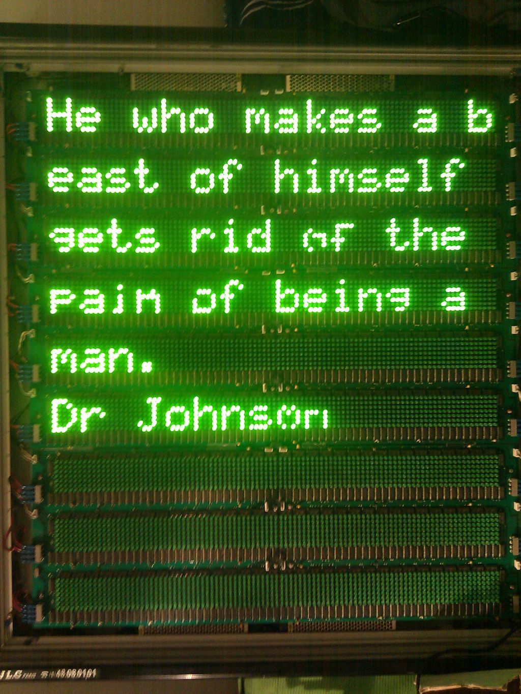
and the second one was a green multiline display

So, here is a little story on how I managed to pwn them.
The one line red display
When we got the display, the power chord was out, so we had to open it to plug one in. The input was a serial db25 connector, plugged to a circuitry where all the ICs where sanded… But on the actual matrix part, there was plenty of 4094 shift registers, and darlington arrays.
So instead of reverse engineering the over engineered and sanded electronic part, we removed all that stuff, and started playing with the few cables available on it. I then took an Arduino, made a combinatory of the inputs by counting on them, to find out what does what. That’s how I finally found out what is the clock and the data. Then a few lines of code later, and we had a serial console to write characters directly on the display… And voila \o/ !
Only trick was that the 4094 is 8 bits, though each column has only 7 LED pixels…
The code is on github :
The multiline green display
Same as the first one, the display had no power chord (I know many are into copper “recycling” but hell, why do they remove it from devices that can work ?!)
This one is a bit more tricky, not only because it is a 9 displays of 8 lines of 7 LED pixels, but also because all the electronics are packaged in a controller outside, a DIN cable connecting directly to the 4094 shift registers. The cable is very fragile and can lead to lost pixels or added pixels when printing out, just by moving it.
At first look, I put my leatherman between the pins and the ground, and I added pixels to the register. Knife hack ! So following step was to plug an Arduino on it, and find out what are the pins. I checked out the parts inside the display (as I opened it to put the power chord back), and found out there was data, /data, clk, /clk and ground.
So, I decided to put negated outputs to HIGH, and play with DATA and CLK to add/remove pixels. I hardcoded a font library into it, same as the first one, and got the device to write what I want. There are escaped characters that are used of testing, and one escaped character that helps switch from text mode to binary mode.
With the binary mode, I wrote a little python script that takes a handmade bitmap and converts it to ordered bits sent to the display.
The code is on github :